GRP Project Timeline
1/9/19 - First told about the project, had to start designing a game.
1/11/19 - Turned in my own game design.
1/16/19 - Worked on Research and History of Educational Robotics.
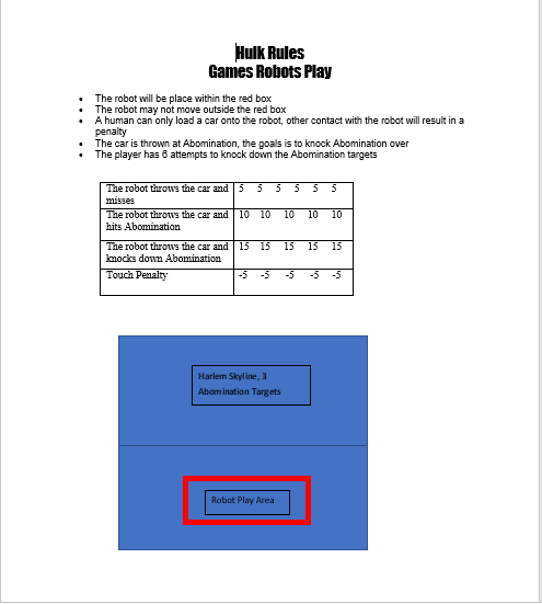
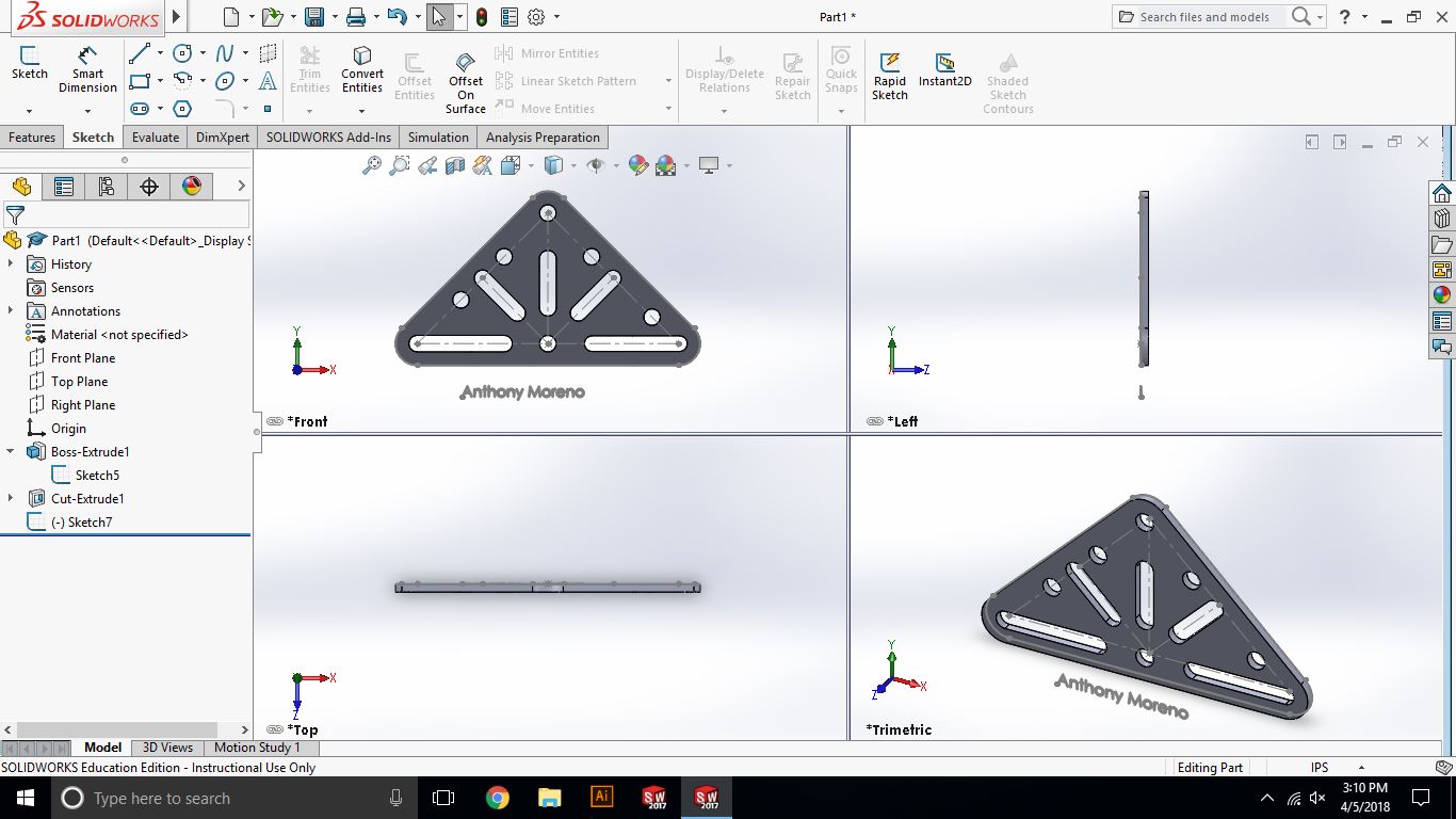
2/6/19 - The class decided to do the Hulk-A-Mole game and worked on a rules sheet for the game.
2/12/19 - Turned in my game board design of the Hulk-A-Mole game.
2/13/19 - Worked on building a Lego Mindstorms Robot and got the EV3 program on a computer.
2/27/19 - Finished building the Lego robot and worked on programming the robot.
3/6/19 - Worked on the the game board and beta testing the game.
1/11/19 - Turned in my own game design.
1/16/19 - Worked on Research and History of Educational Robotics.
2/6/19 - The class decided to do the Hulk-A-Mole game and worked on a rules sheet for the game.
2/12/19 - Turned in my game board design of the Hulk-A-Mole game.
2/13/19 - Worked on building a Lego Mindstorms Robot and got the EV3 program on a computer.
2/27/19 - Finished building the Lego robot and worked on programming the robot.
3/6/19 - Worked on the the game board and beta testing the game.
2/12/19
Hulk-A-Mole Game Board Design
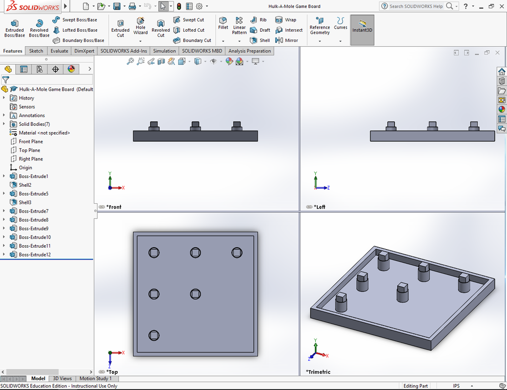
| hulk-a-mole_game_board.sldprt |
1/30/18
Botball Game Review
Botball 2019 - Game Video Intro: https://www.youtube.com/watch?v=BOIF-OFggGo
2019 Botball Table: www.youtube.com/watch?v=Au6Hl8oAIPI
2019 Botball Game Review: https://drive.google.com/file/d/1IP3_P91RLASeBR1TbDe5E-MrOIDh5CqT/view
2019 Botball Seeding Scoring Sheet: https://drive.google.com/file/d/1yKQjjKCiPbwMFkpFA0r0foUaZfwgC6Pj/view
The scenario of the game is that a storm has struck a city and so there are many structure fires and flooding. Each team has two minutes to earn as many points as they can. A team earns points from using firefighters and firetrucks to put out the fires. They use the ambulances to move the uninjured people (green) to the Disaster Relief Zone and the injured (red) to the Medical Complex. A team also earns points from hooking up electrical lines and disconnecting the gas valves. Points are also earned from moving food, water and medical supplies to the Disaster Relief Zone and the Medical Complex. Given a robot to partake in this game, I would aim to move to the firetrucks to the burning buildings, firefighters to the sky bridges, moving the injured and medical supplies to the Medical Complex and to get the Mayor or Botguy, since these offer the most points.
1/16/19
Educational Robotics Research and History
Robotics Competitions: VEXU, BEST, CREATE, FIRST, BotBall
Botball 2018 Video: www.youtube.com/watch?v=JEodSfyNNQA
FIRST 2018 Video: www.youtube.com/watch?v=trHya7SgNTk
VEXU 2018 Video: www.youtube.com/watch?v=kgjPoKhr0Hg
Educational robotics is way to teaching students about STEM (Science, Technology, Engineering and Mathematics) through robotics. As time goes on, there are more advances in technology and robotics is a way for students to learn about technology and to have a hands on experience. Educational robotics is a way of getting students interested in working in the jobs relating to engineering and technology. Educational robotics allows students to learn about designing, testing and using robots. Educational robotics allows students to be more creative and to build out their ideas and helps them build the future.
Games Robot Play Game Design
1/7/19
Numbers Game
First Try
Score: 11 |
Second Try
Score: 15 |
Third Try
Score: 17 |
Fourth Try
Score: 37 |
5S Quality Dividend First Try: 8 Shifts
5S Quality Dividend Second Try: 4 seconds, 1 Shift
Sort, Set in Order, Shine, Standardize, Sustain
What did you learn in this 5S Numbers Game? You should organize your area in order to be able to find something you need as quickly as possible.
How might you incorporate the 5S process into your current workplace? Separate tools by use, organize them in a certain area, and just clean up the workplace and make sure everyone that works in the workplace knows where a tool is.
What difference would you expect it to make? It would make the workplace work more efficient and makes the workplace cleaner and more organized.
LED Pop up Greeting Card 2018
A greeting card is used to show someone sentiment and gratitude. They are usually given in special occasions such as Christmas, birthdays, etc. In 1962, Nick Holonyak Jr. developed the first light-emitting diode that showed light in the visible of the frequency range. In 1972, M. George Craford mad the first yellow LED and a brighter red LED than Holonyak. In 1979, Shuji Nakamura made the first blue LED.
11/30- Wrote the paragraph that is going to be placed inside of the greeting card
12/3- Looked online for ideas of what to do for the pop up element of the card.
12/4- Started to see how the program where we would plan our circuits worked.
12/5- Made my greeting card sketch and planned my circuit for the card.
12/7- Got the inkscape program and started to watch the videos on the hub about making my greeting card design.
12/10- Made the design of the outside of the greeting card
12/11- Made the design of the inside of the greeting card, printed out the design, made my pop up element and sketch the circuit.
12/12- Got the materials, and made the circuit and decorated the card.
|
|


|

|

|
Lantern Project

|
|
The Moon Festival or the Mid-Autumn Festival falls on the 15th day of the 8th month of the Chinese Lunar Calendar. It is when the moon is at its brightest and roundest. It is one important traditional Chinese event, it is an occasion for family reunions.
Oct. 2nd - We went online decided on what design we wanted to use and we decided to do a cylinder shaped lantern, we then sketched out our lantern design.
Oct. 3rd - We started and finished the wire frame for our lantern. We first cut out 4, 12 inch wires and then we made two circles for the top and bottom. We tied the 4 wires on the two circles, and then we added a platform in the middle for the candle.
Oct. 5th - We got our wire frame and started to wrap and glue pink tissue paper around our frame. After we were done putting tissue paper around the frame we put in the candle on a platform we made in the middle and tied the string so we could hang up the lantern.
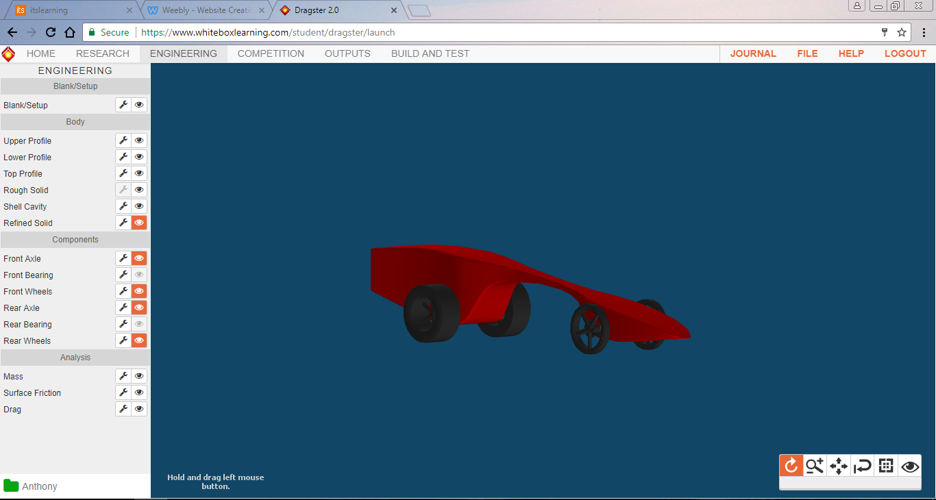
Dragster Project
This is the second project we've worked on so far. I decided to build a dragster car. The history behind these dragster cars started in England but then got popular in the United States in the late 50's early 60's. It was in the 1970's that dragster racing became more than a pass time. Ohio State University helped make a curriculum, in which one of the projects was to make a dragster car that was powered by CO2.
Day 1- We were told about how you had choice of what project you wanted to do. I decided to build the dragster car.
Day 2- Went on Whitebox and read the background information and did the quizzes.
Day 3- Started to the design my dragster car. Took a while to figure out how to design it but I eventually figured it out.
Day 4- I had my design and got it printed out and got the kit. I cut the dragster to the appropriate shape.
Day 5- Once I had the shape of the dragster, I put the axles and attached the wheels and added electrical tape for decoration.
Once I finished reading about the background information and taking the quizzes, I started to design my dragster car. At first I couldn't figure out how to change the shape of the car, but eventually got the hang of it and came up with my design. I then got my kit and got my design printed out. I started out by gluing the side profile of the car to the block of wood first. Then I started to shave it to shape with a knife. Once I had the shape roughly cut out, I sanded it so it was smooth. I also drilled the holes where the axles were going to go. Then I proceeded to work on the top profile of the dragster car. I cut down to shape and sanded it smooth. Once I had the body of dragster car, I put the axles through the holes I previously drilled and attached the wheels. I didn't want it to be that plain, I added some electrical tape to add some decoration.
|
|
For the first project of the second semester I decided to make a sticker with the vinyl cutter. Vinyl was first invented in the early 1920s by a rubber scientist who was trying to find an synthetic adhesive. Vinyl is a synthetic man-made material, it is made from ethylene and chlorine. A vinyl cutter is a computer-controlled machine. The vinyl cutter we are using is the CAMM-1 Pro Series GX-500 Vinyl Cutter by Roland. The vinyl cutter can cut up to 33 inches per second. It has the mechanical resolution of 0.0005”.
Day 1- We got to chose what project we wanted to do, I decided to do the vinyl cutter project.
Day 2- Worked doing background research on the history of vinyl and the vinyl cutter.
Day 3- Didn't have class
Day 4- Did more background research
Day 5- Took a quiz about the project
Day 6- Went on Adobe Illustrator and started to make my design.
Day 7- I finished making my design in Adobe Illustrator.
Day 8- I cut out my design using the vinyl cutter.
Day 9- I got the transfer tape and got the black parts of the design and placed it on top of the yellow circle and then I was done with the project.
Day 10- Didn't have class
Day 11- Worked on finishing my weebly page
Day 12- Didn't work on anything
Day 13- Didn't work on anything
I started out by doing background research on the history of vinyl and the vinyl cutter, then I was given a quiz about the project and the research we did. After that I got on to Adobe Illustrator and started to make my design. I decided to go with a logo of a soccer team. I made the logo in two different parts. I first made a circle for the yellow part of the logo and one for the black parts of the logo. I added 2 rectangles on the top to help me line up the two parts later on. Then I went to the vinyl cutter and cut out my design. After I was done cutting out the design, I got transfer tape and got the black parts of the design and lined it up on top of the yellow circle and then I was done with the project.
|
|

|

|
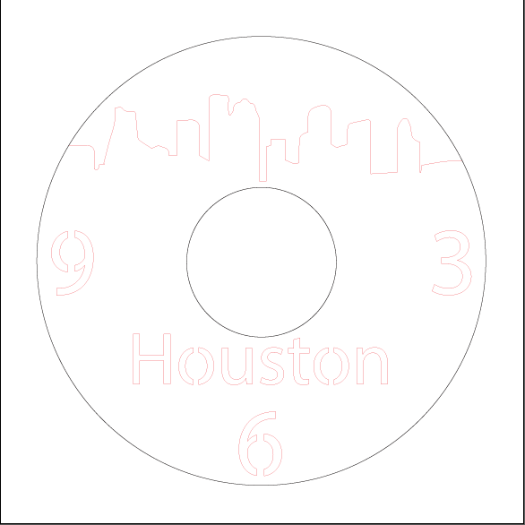
Vinyl Record ClockFor the second project of the second semester I had to make a vinyl record clock. The first laser cutter machine was manufactured by Western Electric Engineering Research Center in 1965. In 1967 the British pioneered the laser cutting of metals and during this time CO2 lasers were used to cut non-metals.
Day 1- I was told about the project, we were tasked with creating a clock using a vinyl record. Day 2- Looking for designs and ideas Day 3- Didn't have class Day 4- Still looking for a design for the clock Day 5- Decided to go with the Houston skyline for the design Day 6- Looked at videos of the process to build the clock. Bought my materials needed for the project. Day 7- The teacher showed us how to start making your design on Adobe Illustrator Day 8- Didn't have class Day 9- Starting working on making my design Day 10- Got the skyline on top of the design done. Day 11- Worked on the numbers and the Houston on the bottom of the design Day 12- Tried to figure out how to keep the circles in the middle of the 6, 9 and the O's in Houston from falling off. Day 13- Didn't have class Day 14- Fixed the circles and got the design done. |
SolidWorks
For the third project of the second semester we worked on a program called SolidWorks. SolidWorks was founded in 1993 by Jon Hirschtick. To set up the company he used $1 million he made while at the MIT Blackjack Team. He recruited a team of engineers with the explicit purpose of making 3D CAD technology more accessible. SolidWorks first released on November 1st, 1995. In 1997, Dassault Systèmes acquired SolidWorks for $310 million in stocks.
Timeline
Day 1- Talked about school safety procedures
Day 2- Talked about school safety procedures
Day 3- Started by doing background research on SolidWorks
Day 4- Started to watch the two videos from the HUB explaining how to make Lego pieces
Day 5- Continued watching the videos and wrote down the steps.
Day 6- Finished writing down the steps of the two videos.
Day 7- Worked on the quiz
Day 8- Worked on designing the pvc pipe.
Day 9- FInished making the pvc pipe.
Day 10- Worked on my weebly
Day 11- FInished updating my weebly
Quiz
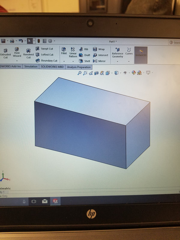
Making the rectangular prism
1. I selected the front plane, and then clicked sketch.
2. I sketched a corner rectangle, then selected smart dimension, i made the height 2.5 in and the length 5 in.
3. I clicked Extruded Boss/Base and selected the rectangle and made the width 2.5 in.
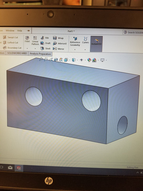
Making the holes
1. I selected a side face and sketched a circle.
2. I selected the circle and clicked Extruded Cut and made it 5 in.
3. I selected the front face and sketched two circles.
4. Selected one circle and clicked Extruded Cut and made it 2.5 in. Then selected the other circle and clicked Extruded Cut and also made it 2.5 in.
Making the handle
1. I selected the bottom face of the prism
2. I sketched a circle and the selected smart dimension and made the distance between the center circle and the side 2.5 in and made the distance from the top 1.25 in.
3. Then I clicked exit sketch and the selected the circle
4. WIth the circle selected, I clicked on Extruded Boss/Base to make the handle. I made the handle 5 in long.
PVC Pipe
1. I first started by sketching a circle on front plane. I made the radius 2 in.
2. Then I clicked on Extruded Boss/Base and clicked the circle
3. I made the height of the cylinder 8 in tall.
4. Then I went to the top face of the cylinder and sketched a smaller circle with a radius of 1.8 in.
5. I selected the smaller circle and selected Extruded Cut.
6. Then I went on the Right Plane and sketched a circle that had a radius of 2 in. in the middle of the first cylinder I made.
7. I selected the circle and clicked Extruded Boss/Base and made it 8 in and changed Blind to Mid Plane so it would be in the middle of the other cylinder.
8. I made a smaller circle that had a radius of 1.8 in.
9. Selected Extruded Cut and selected Through All so it would cut through the other cylinder.
Summary
I began by doing background history on SolidWorks. After I was done with the background research, we had to watch two videos about making Lego bricks.
I watched both of them and explained the steps. Then we had to do the quiz, we had to make a rectangular prism, then add 3 holes and then add a handle and then explain the steps for each one. Finally we had to design a 4 joint PVC pipe and then explain the steps and then I was done.
Timeline
Day 1- Talked about school safety procedures
Day 2- Talked about school safety procedures
Day 3- Started by doing background research on SolidWorks
Day 4- Started to watch the two videos from the HUB explaining how to make Lego pieces
Day 5- Continued watching the videos and wrote down the steps.
Day 6- Finished writing down the steps of the two videos.
Day 7- Worked on the quiz
Day 8- Worked on designing the pvc pipe.
Day 9- FInished making the pvc pipe.
Day 10- Worked on my weebly
Day 11- FInished updating my weebly
Quiz
Making the rectangular prism
1. I selected the front plane, and then clicked sketch.
2. I sketched a corner rectangle, then selected smart dimension, i made the height 2.5 in and the length 5 in.
3. I clicked Extruded Boss/Base and selected the rectangle and made the width 2.5 in.
Making the holes
1. I selected a side face and sketched a circle.
2. I selected the circle and clicked Extruded Cut and made it 5 in.
3. I selected the front face and sketched two circles.
4. Selected one circle and clicked Extruded Cut and made it 2.5 in. Then selected the other circle and clicked Extruded Cut and also made it 2.5 in.
Making the handle
1. I selected the bottom face of the prism
2. I sketched a circle and the selected smart dimension and made the distance between the center circle and the side 2.5 in and made the distance from the top 1.25 in.
3. Then I clicked exit sketch and the selected the circle
4. WIth the circle selected, I clicked on Extruded Boss/Base to make the handle. I made the handle 5 in long.
PVC Pipe
1. I first started by sketching a circle on front plane. I made the radius 2 in.
2. Then I clicked on Extruded Boss/Base and clicked the circle
3. I made the height of the cylinder 8 in tall.
4. Then I went to the top face of the cylinder and sketched a smaller circle with a radius of 1.8 in.
5. I selected the smaller circle and selected Extruded Cut.
6. Then I went on the Right Plane and sketched a circle that had a radius of 2 in. in the middle of the first cylinder I made.
7. I selected the circle and clicked Extruded Boss/Base and made it 8 in and changed Blind to Mid Plane so it would be in the middle of the other cylinder.
8. I made a smaller circle that had a radius of 1.8 in.
9. Selected Extruded Cut and selected Through All so it would cut through the other cylinder.
Summary
I began by doing background history on SolidWorks. After I was done with the background research, we had to watch two videos about making Lego bricks.
I watched both of them and explained the steps. Then we had to do the quiz, we had to make a rectangular prism, then add 3 holes and then add a handle and then explain the steps for each one. Finally we had to design a 4 joint PVC pipe and then explain the steps and then I was done.

|
|

SolidWorks Cont.
Assembly of the Parts
Hex Standoff
Triangle Plate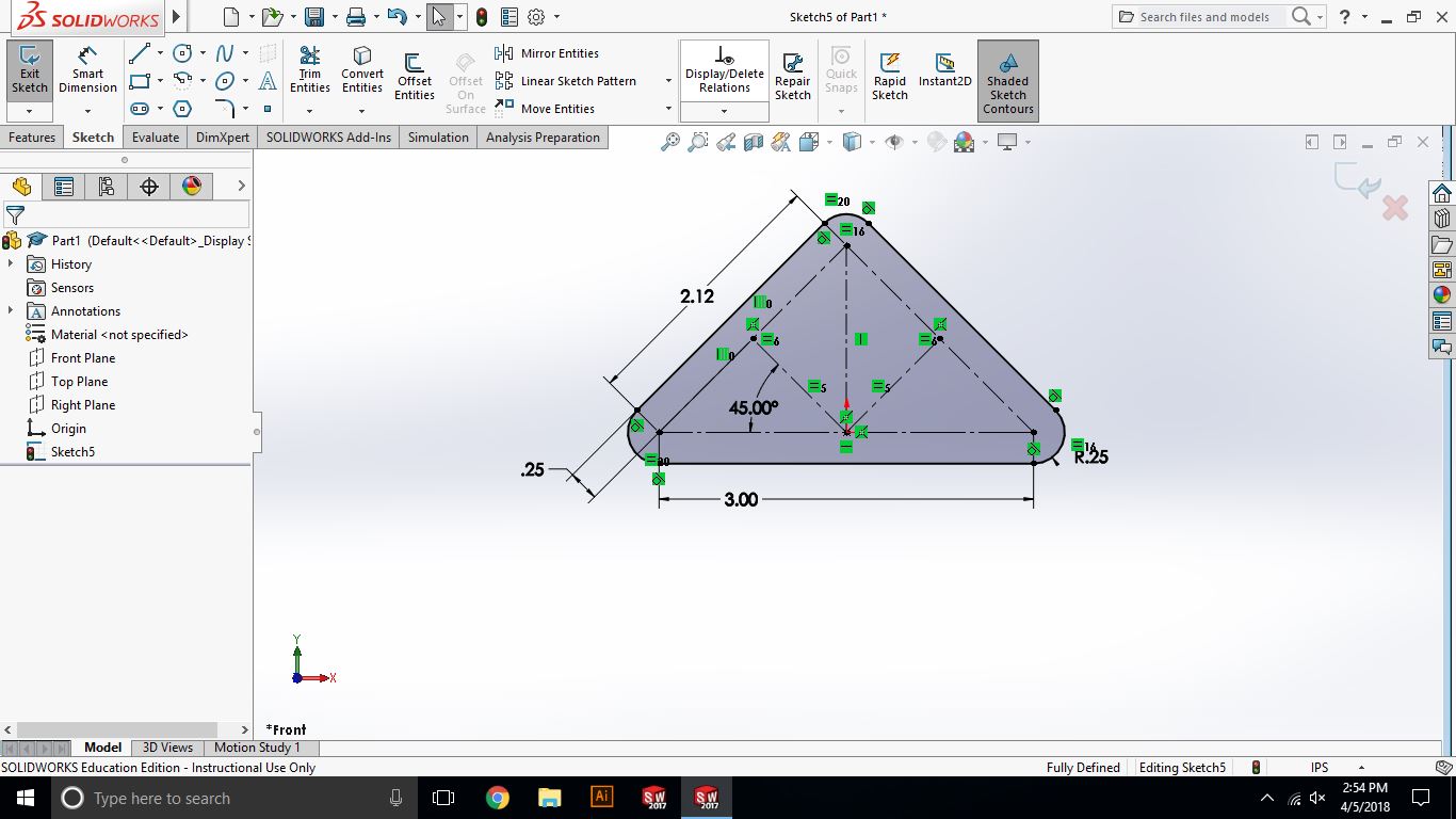
Angle
Screw
Assembly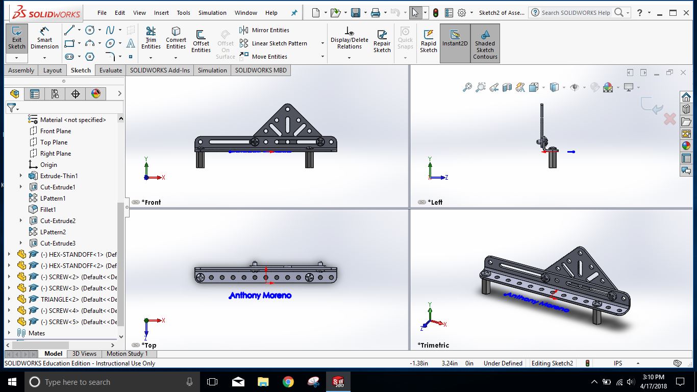
|
Timeline:
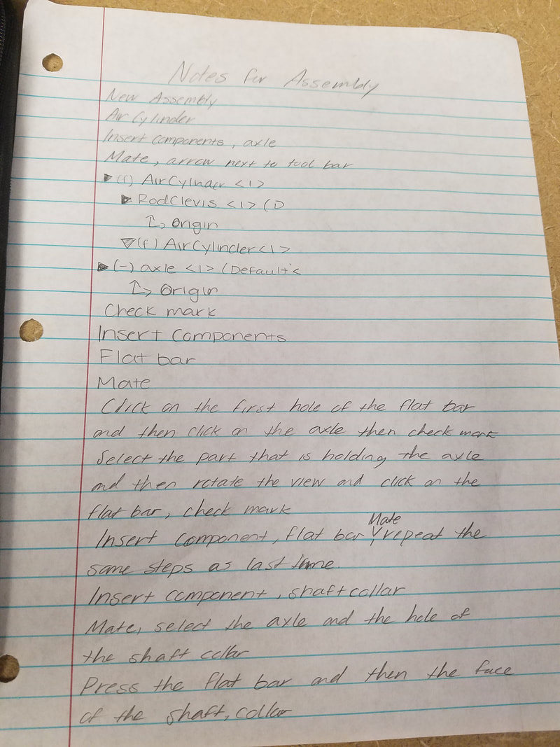
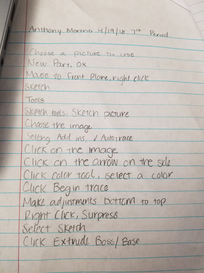
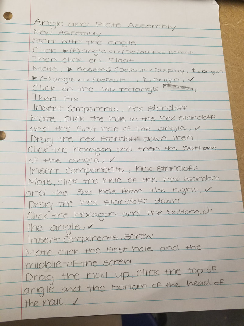
Day 1- Took notes Day 2- Went on Solidworks and made the Axle Rod and Shaft-Collar Day 3- Worked on SolidWorks to make a 9 Hole Flat Bar. Day 4- Watched a video on how to assemble the parts and took notes. Day 5- Took a quiz by going on SolidWorks seeing if I could assemble the parts and made sure it would move without falling apart. Day 6- Started to take notes on the next the parts Day 7- Continue taking notes over the parts Day 8- Finished taking notes Day 9- Started working on making the actual parts Day 10- Continue making the parts Day 11- Took notes on how to convert an image from 2D to 3D Day 12- Chose an image and make it from 2D to 3D with the notes we took. Day 13- Worked on updating my weebly. Axle Rod Steps
I sketched a circle that had a diameter of .188 in. Then I went to features and clicked on Extruded Boss/Base. Then made the measurement 1.375 in. Shaft-Collar Steps I first sketched a circle that had the diameter of .438 in and then I went to features and click on Extruded Boss/Base and made the measurement .25 in. Then on went on one the the bases and sketched another circle that had a diameter of .19 in. Then went to features again and clicked on Extruded Cut and cut through all. 9 Hole Flat Bar Steps While making the 9 hole flat bar, I learned how to make a straight slot since that was the shape of the the flat bar and I learned how to do a linear pattern since you just needed to make the circle and make 8 more copies instead of making 9 separate holes. 3D Logo Steps I decided to the Puma logo, I went on SolidWorks, New Part, Ok. I went on the front plane and went to Sketch Tools and then Sketch Picture and selected the Puma Logo. Went to Add-Ins, and then Autotrace. Then went to the arrow and the selected the color. I selected the White and and clicked Begin Trace. I made my adjustments, then I right clicked and then surpress and then Extruded Boss/Base.
|


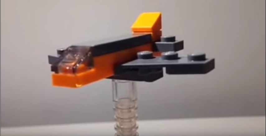
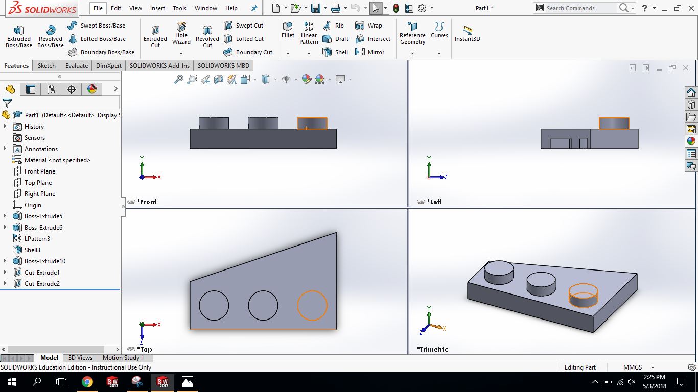
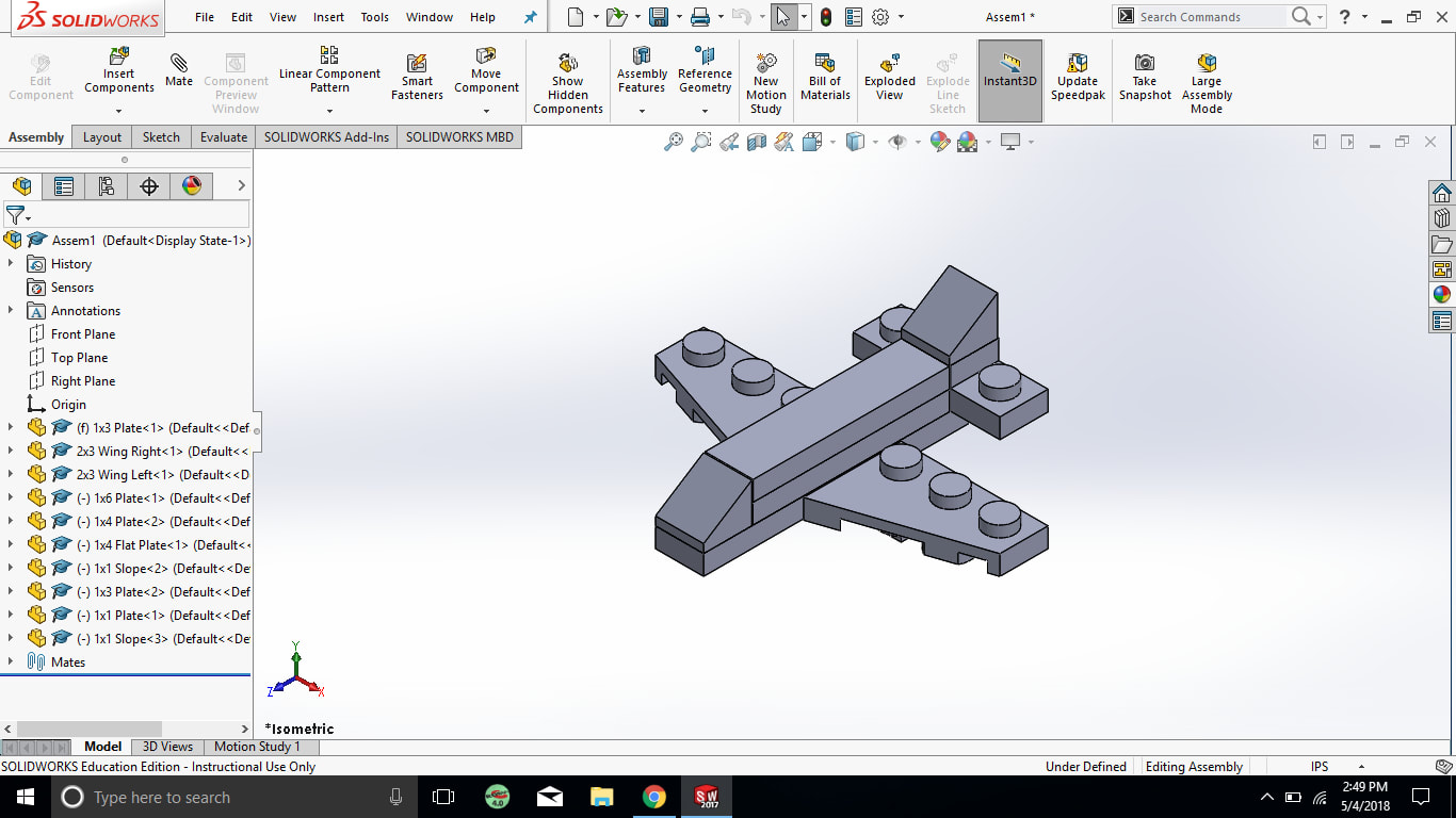
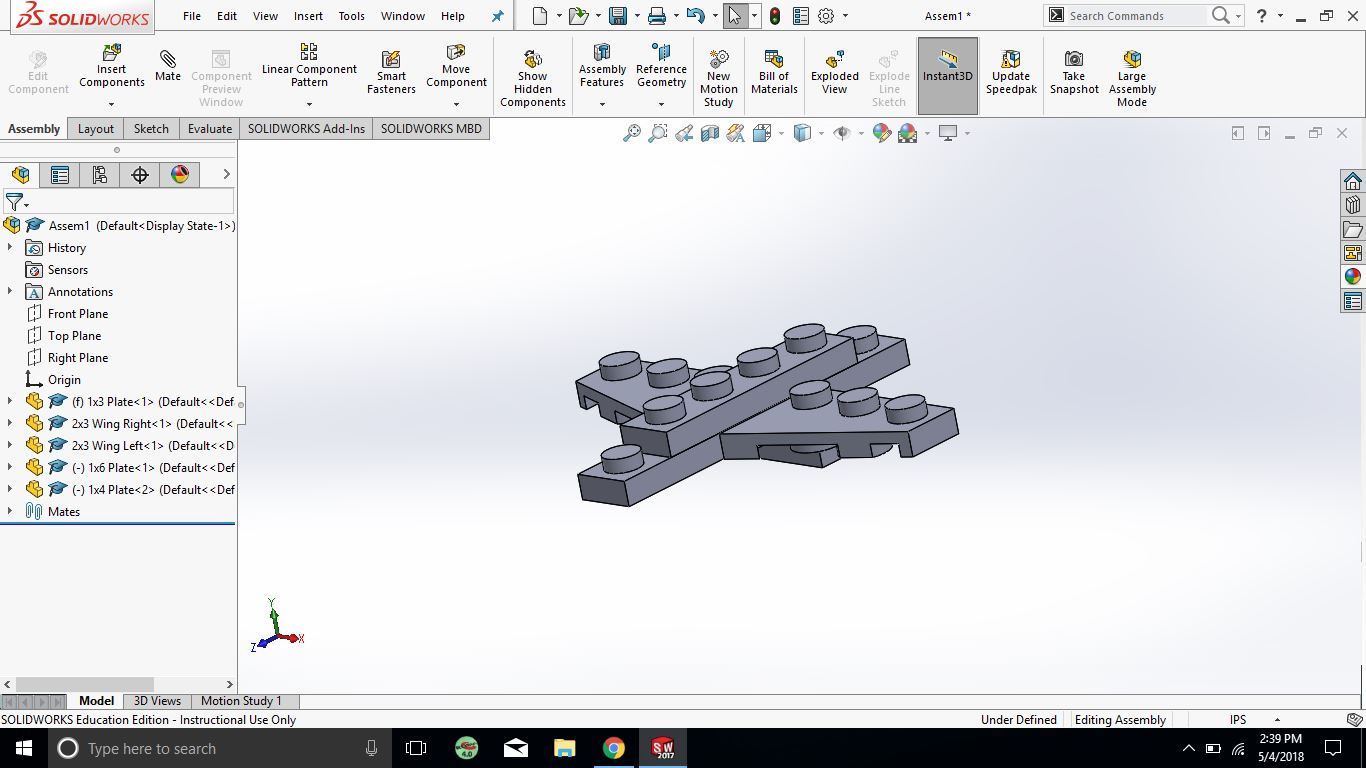
Toy in SolidWorks
Timeline:
Day 1- Told that we had to make a toy
Day 2- Didn't know what to do exactly, just knew I wanted to do LEGO
Day 3- Decided to go with a LEGO plane I saw in a youtube video.
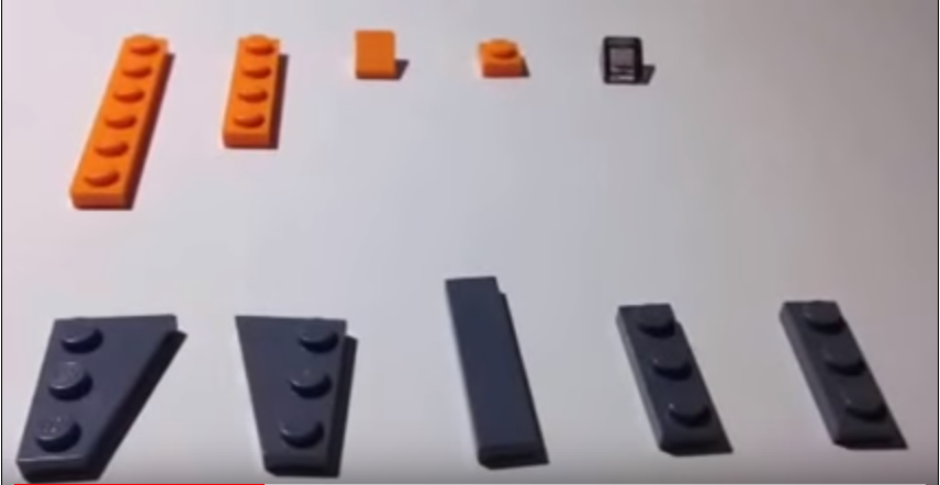
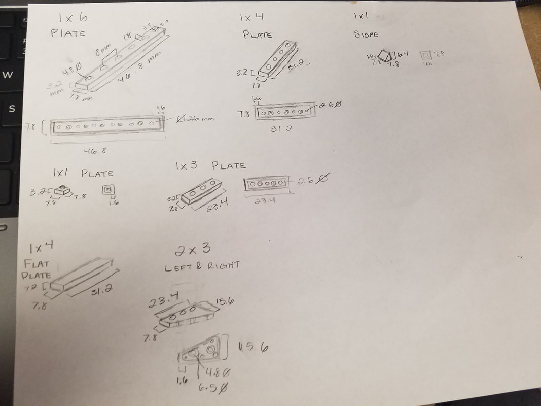
Day 4- Found the measurements for each of the pieces needed to build the plane.
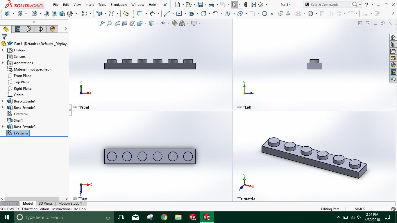
Day 5- Made the 1x6 Plate, the 1x4 Plate and the 1x1 Slope Piece
Day 6- Made the 1x Plate, 1x3 Plate, 1x4 Flat Plate
Day 7- Didn't have class today.
Day 8- I worked on the 2x3 Wing Right and 2x3 Wing Left Plates
Day 9- Assembled my pieces together to make the plane.
Day 1- Told that we had to make a toy
Day 2- Didn't know what to do exactly, just knew I wanted to do LEGO
Day 3- Decided to go with a LEGO plane I saw in a youtube video.
Day 4- Found the measurements for each of the pieces needed to build the plane.
Day 5- Made the 1x6 Plate, the 1x4 Plate and the 1x1 Slope Piece
Day 6- Made the 1x Plate, 1x3 Plate, 1x4 Flat Plate
Day 7- Didn't have class today.
Day 8- I worked on the 2x3 Wing Right and 2x3 Wing Left Plates
Day 9- Assembled my pieces together to make the plane.
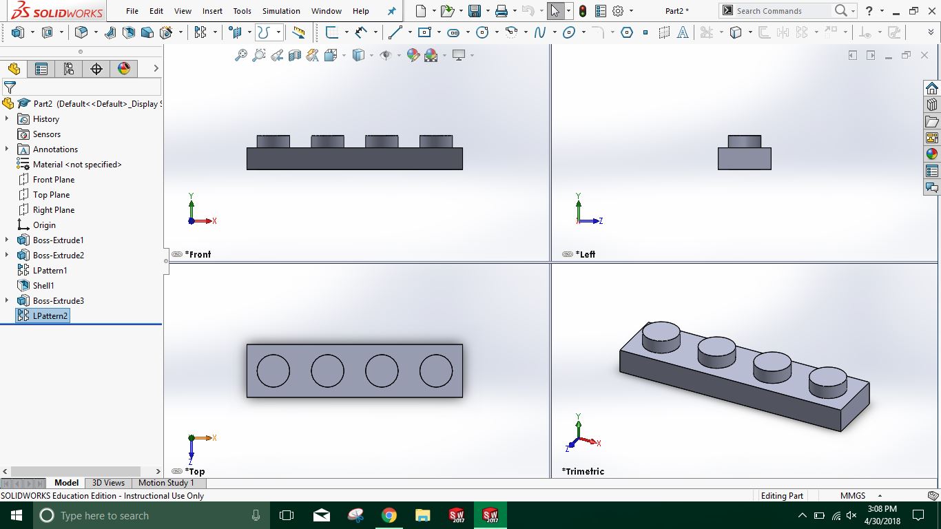
Steps for creating a 2x4 Lego piece
1. When you open SolidWorks and when the new document window pops up, you select Part and then Ok.
2. Select the front plane and then click sketch, select sketch rectangle.
3. Click on the origin which is the middle of the two red arrows and then drag out a box.
4. Select smart dimension and click on one of the widths and make it 5/8 in and then select one of the lengths and make it 5/4 in.
5. Click on Extruded Boss/Base and click on the rectangle make the measurement of the height 3/8 in.
6. Go to sketch and draw select sketch a circle on the rectangle. Then select smart dimension and make the diameter 3/16 in.
7. Click Extruded Boss/Base and click on the circle and make the height of the stud 1/16in.
8. Create a linear pattern and make the brick have 4 studs across and 2 studs down and evenly space them out.
9. Go to the bottom of the brick and click shell and make the shell thickness 1/16 in.
10. Make circle on the bottom of the brick that has the diameter 1/4 in. Make the circle 5/16 in from the top and the side.
11. Click on Extruded Boss/Base and click on the circle you just created and make the height 3/8-1/16 in. Uncheck the merge result box.
12. Shell the cylinder you just created and make the shell thickness 1/32 in.
13. Boss Extrude and the Shell you just did and create a linear pattern, make it parallel to the bottom make 3 pegs and make the distance between them 5/16 in. Then you are done.
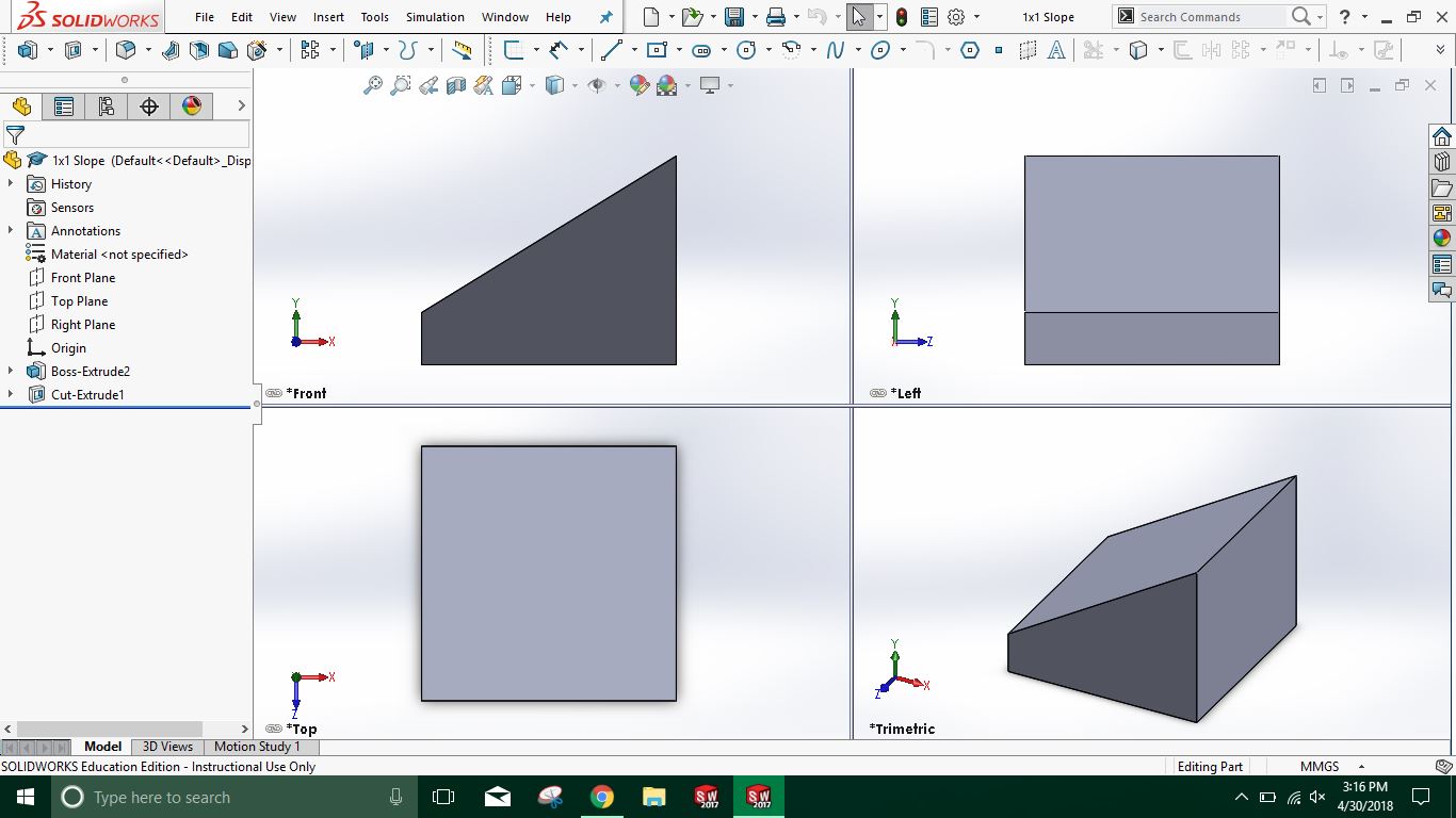
Steps for creating a slanted Lego piece
1. Make the the units MMGS
2. Create a new sketch on the top plane, select corner rectangle and make a 48 mm by 24 mm corner rectangle, then exit sketch.
3. Select Extruded Boss/Base and make the height of the brick 23.4 mm.
4. Select the top rectangle and click sketch and press CTRL+8 on your keyboard.
5. Sketch a circle and select smart dimension and make the diameter 15 mm. Then make the distance from the center of the circle from the left 12 mm and the distance from the center of the circle and the top 12 mm as well. Exit Sketch
6. Click on Extruded Boss/Base and make the height of the stud 5.1 mm.
7. Select the front face of the prism and then click sketch and press CTRL+8 on your keyboard.
8. Sketch a line from near the bottom of the right edge to the middle of the top edge. Then make a line for the the top corner to the right corner and the a line from the the right corner to the bottom corner making a triangle.
9. Click Smart Dimension and make the distance between the bottom corner of the rectangle and the line 5.1 mm. Make the distance between the top point of the line and the left corner of the prism 24 mm.
10. Go to features tab and select Extruded Cut and make sure the triangle is selected and then change the option in the Direction 1 box from Blind to Through All and then click the green check mark.
11. Click Shell and the select the bottom face of the prism and make the shell thickness 3 mm. Then you are done.
1. When you open SolidWorks and when the new document window pops up, you select Part and then Ok.
2. Select the front plane and then click sketch, select sketch rectangle.
3. Click on the origin which is the middle of the two red arrows and then drag out a box.
4. Select smart dimension and click on one of the widths and make it 5/8 in and then select one of the lengths and make it 5/4 in.
5. Click on Extruded Boss/Base and click on the rectangle make the measurement of the height 3/8 in.
6. Go to sketch and draw select sketch a circle on the rectangle. Then select smart dimension and make the diameter 3/16 in.
7. Click Extruded Boss/Base and click on the circle and make the height of the stud 1/16in.
8. Create a linear pattern and make the brick have 4 studs across and 2 studs down and evenly space them out.
9. Go to the bottom of the brick and click shell and make the shell thickness 1/16 in.
10. Make circle on the bottom of the brick that has the diameter 1/4 in. Make the circle 5/16 in from the top and the side.
11. Click on Extruded Boss/Base and click on the circle you just created and make the height 3/8-1/16 in. Uncheck the merge result box.
12. Shell the cylinder you just created and make the shell thickness 1/32 in.
13. Boss Extrude and the Shell you just did and create a linear pattern, make it parallel to the bottom make 3 pegs and make the distance between them 5/16 in. Then you are done.
Steps for creating a slanted Lego piece
1. Make the the units MMGS
2. Create a new sketch on the top plane, select corner rectangle and make a 48 mm by 24 mm corner rectangle, then exit sketch.
3. Select Extruded Boss/Base and make the height of the brick 23.4 mm.
4. Select the top rectangle and click sketch and press CTRL+8 on your keyboard.
5. Sketch a circle and select smart dimension and make the diameter 15 mm. Then make the distance from the center of the circle from the left 12 mm and the distance from the center of the circle and the top 12 mm as well. Exit Sketch
6. Click on Extruded Boss/Base and make the height of the stud 5.1 mm.
7. Select the front face of the prism and then click sketch and press CTRL+8 on your keyboard.
8. Sketch a line from near the bottom of the right edge to the middle of the top edge. Then make a line for the the top corner to the right corner and the a line from the the right corner to the bottom corner making a triangle.
9. Click Smart Dimension and make the distance between the bottom corner of the rectangle and the line 5.1 mm. Make the distance between the top point of the line and the left corner of the prism 24 mm.
10. Go to features tab and select Extruded Cut and make sure the triangle is selected and then change the option in the Direction 1 box from Blind to Through All and then click the green check mark.
11. Click Shell and the select the bottom face of the prism and make the shell thickness 3 mm. Then you are done.
|
|
|

|


|

|
|
Tape Dispenser
|
