5/8/19
Lessons
| lesson_1.sldprt |
| lesson_2.sldprt |
| lesson_3.sldprt |
| lesson_4.sldprt |
| lesson_5.sldprt |
| lesson_6.sldprt |
| lesson_7.sldprt |
| lesson_8.sldprt |
5/1/19
Basic and Intermediate Part Creation
Basic Part - Not Modified
|
|
Basic Part - Modified
|
|
| basic_part_5-1-19.sldprt |
Intermediate Part
|
|
| intermediate_part.sldprt |
4/24/19
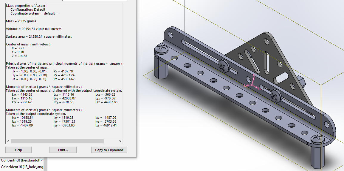
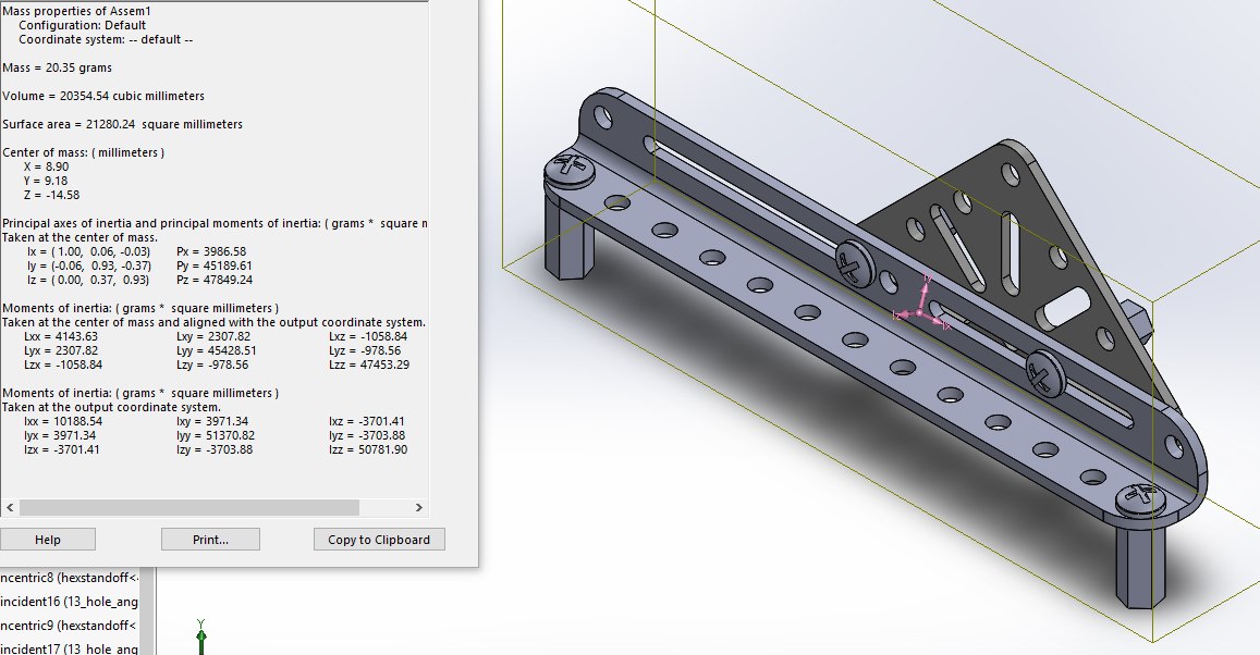
Flat Triangle Assembly
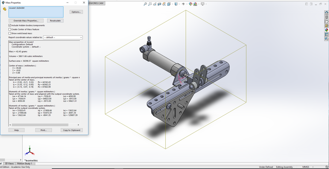
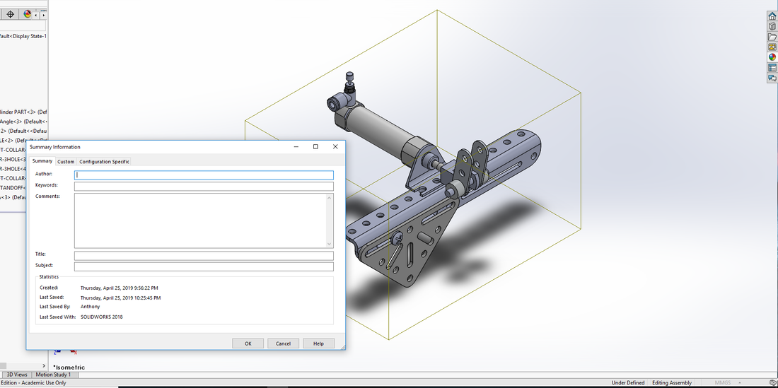
| assem1.sldasm |
4/24/19
Intermediate Part 1
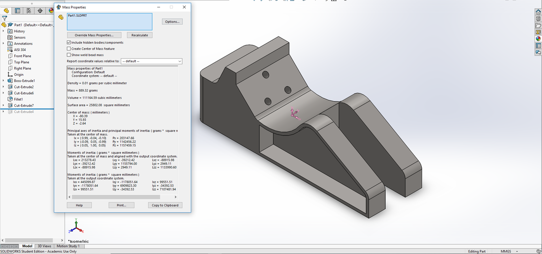
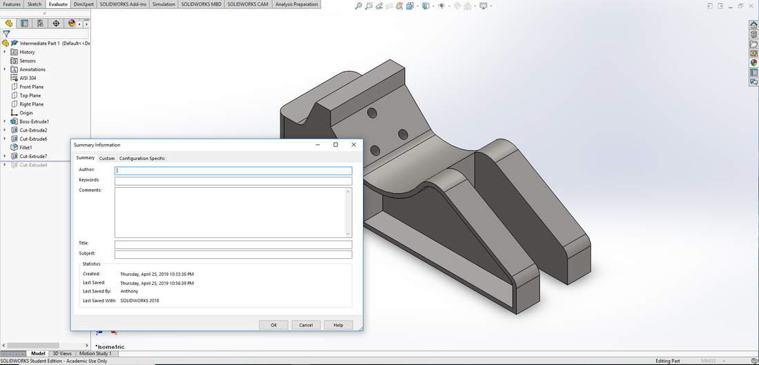
| intermediate_part_1.sldprt |
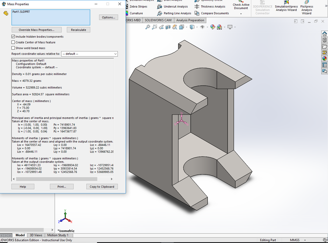
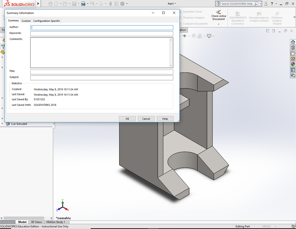
4/22/19
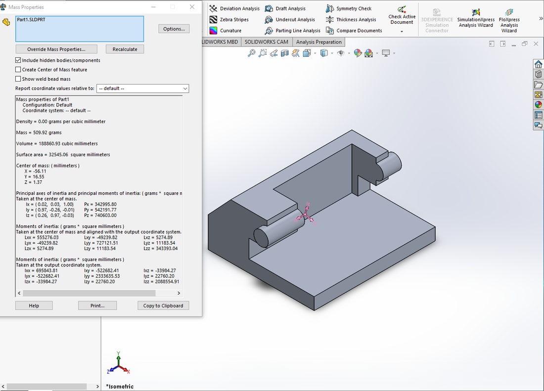
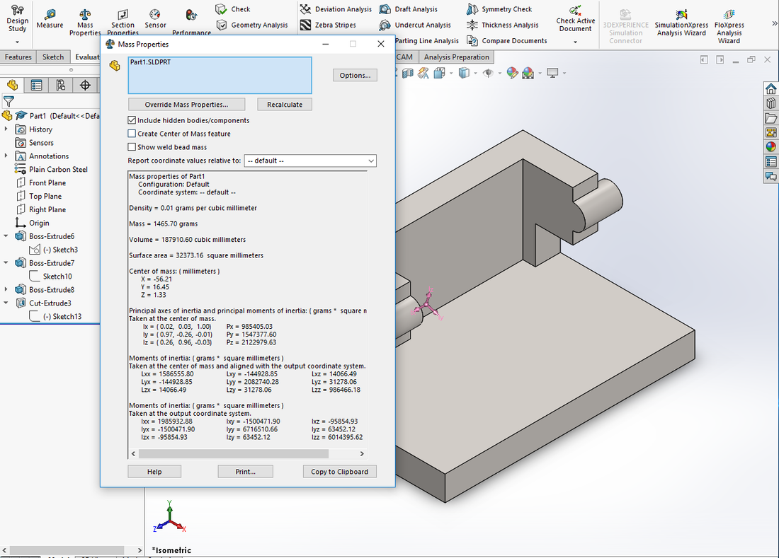
Center of Mass - Total Mass
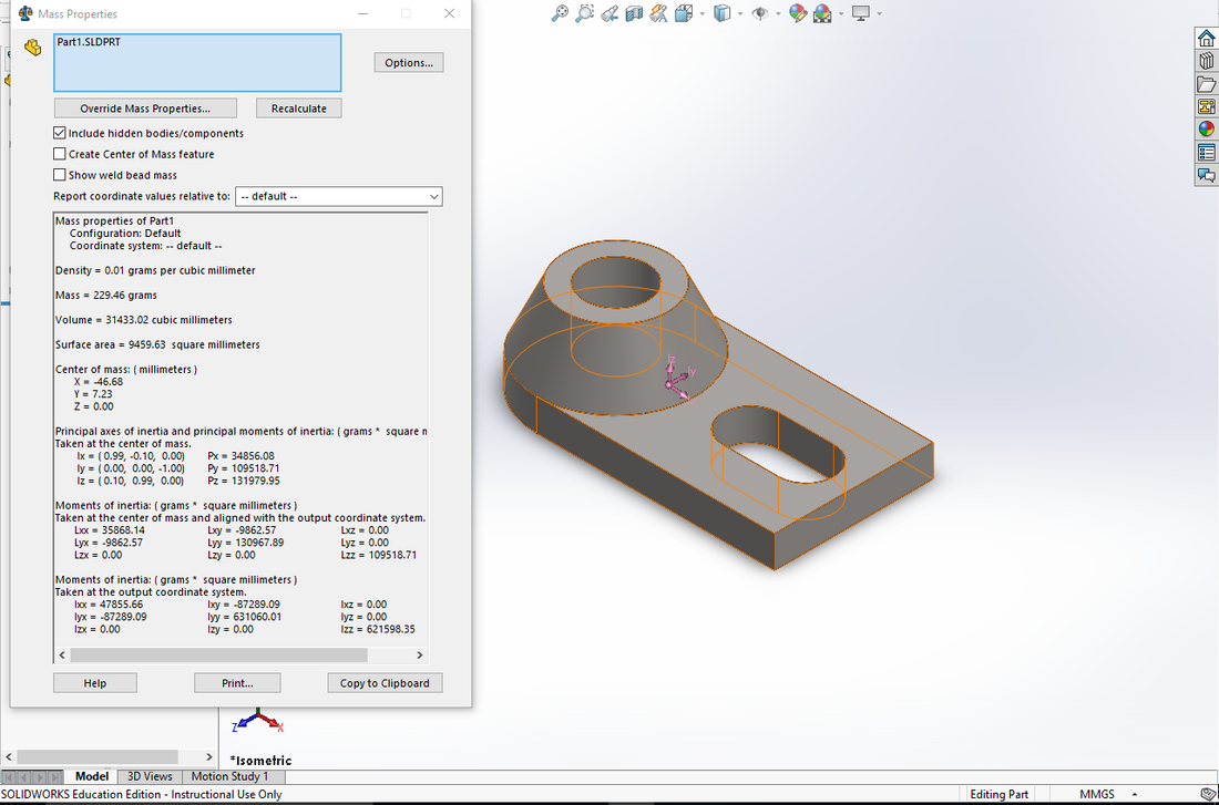
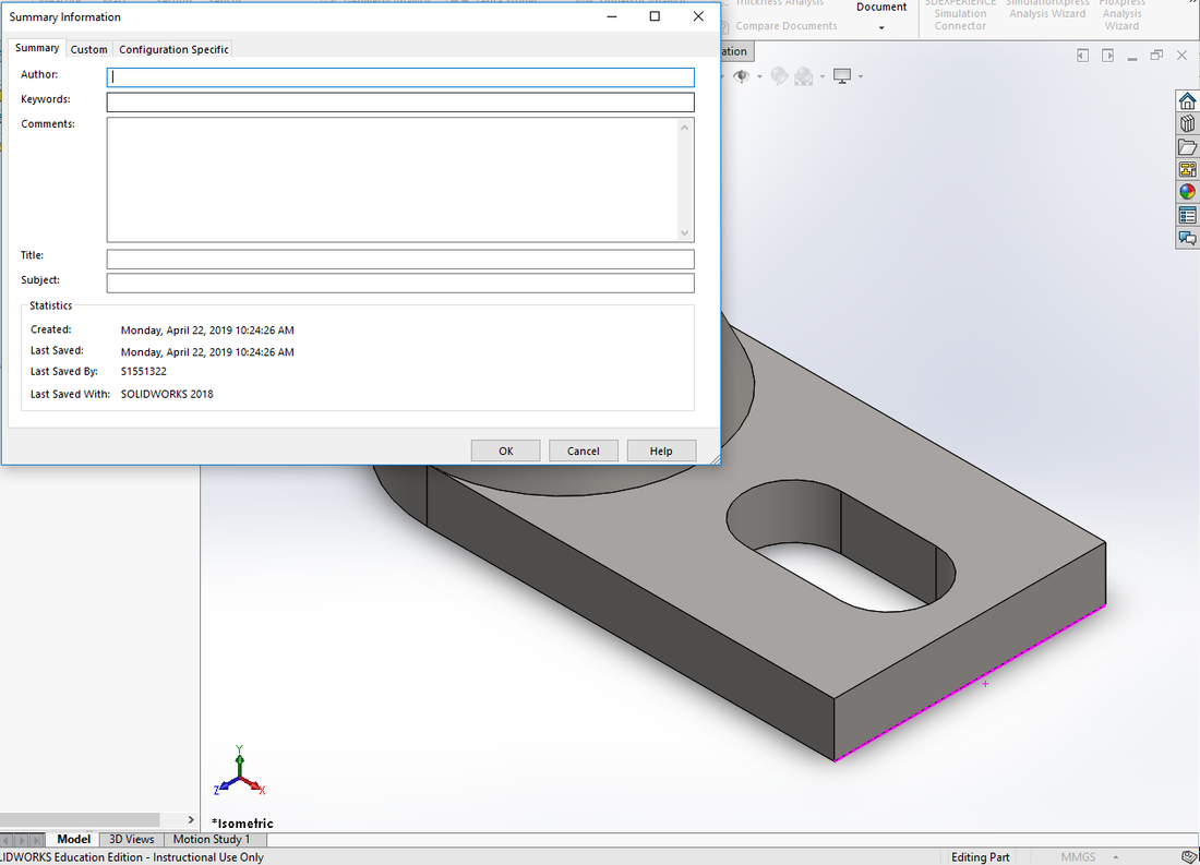
| part.sldprt |
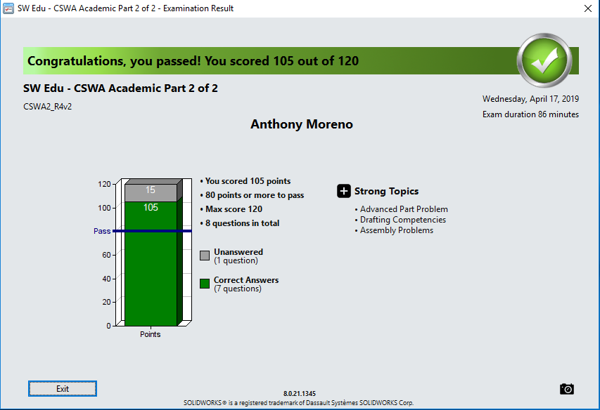
4/17/19
CSWA Exam Part 2
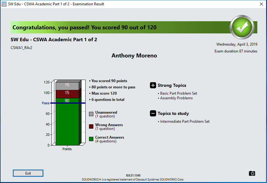
4/3/19
CSWA Exam Part 1
3/25/19
Assembly #2
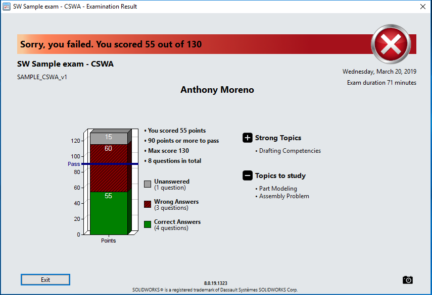
3/20/19
Practice CSWA Exam
3/19/19
Assembly #1
2/25/19 Solidworks Practice
2/18/19 Solidworks Practice Problem
| sw_february_18.sldprt |
Building a 4-way PVC Connector
Steps
1. Create a circle at the origin
2. Smart dimension the circle to 2.5 inches
3. Extrude Boss/Base and make the height 5 inches.
4. Select the top plane and make a circle.
5. Smart dimension the circle to 2.5 inches
6. Smart Dimension and click on the center of circle and then click the right edge, make the distance 2.5 inches.
7. Align the center of the circle with the origin
8. Extrude Boss/Base, Mid-plane and make the height 5 inches.
9. Click on the circle that is on the front plane, and hit CRTL+8
10. Make another circle, smart dimension the distance between the inner circle and the outer circle to 0.2 inches
11. Select the inner circle, Extruded Cut, and make it Through All
12. Click the circle on the top plane and hit CRTL+8
13. Make another circle, smart dimension the distance between the inner circle and the outer circle to 0.2 inches
14. Select the inner circle, Extruded Cut and make it Through All
Feedback: The 4-Way PVC Connector wasn't that difficult to do since I made the PVC Connector on Solidworks last year.
Solidworks Drafting Competencies
1/27/18

Section View: The model is displayed as if cut by planes and faces that you specify, to show the internal construction of the model.

Isometric View: representing three-dimensional objects in two dimensions.
Broken Out Section View: Cuts away a portion of an assembly in a drawing view to expose the inside.
|
Crop View: Focuses on a portion of a drawing view by hiding all but a defined area.

Aligned Section: Typically used for sectioning features that would appear foreshortened in regular section views.
Alternate Position View: Alternate Position Views indicate the range of motion of an assembly component by showing it in different positions.
|
Projected View: Projected views are created by folding off an existing view in one of eight possible projections.
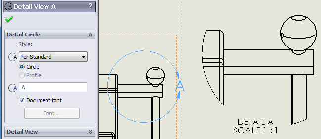
Detail View: Used to show a portion of a view, usually at an enlarged scale.

Break View: Make it possible to display the drawing view in a larger scale on a smaller size drawing sheet.
|
